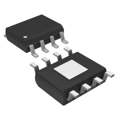
L5973D013TR
Part Number: L5973D013TR
Manufacturer: STMicroelectronics
Description: IC REG BUCK ADJ 2.5A 8HSOP
Shipped from: Shenzhen/HK Warehouse
Stock Available: Check with us
ICRFQ.com - Electronic Components Distributor in China Since 2003

Part Number: L5973D013TR
Manufacturer: STMicroelectronics
Description: IC REG BUCK ADJ 2.5A 8HSOP
Shipped from: Shenzhen/HK Warehouse
Stock Available: Check with us
| Datasheet | |
|---|---|
| Category | Integrated Circuits (ICs) |
| Family | PMIC – Voltage Regulators – DC DC Switching Regulators |
| Manufacturer | STMicroelectronics |
| Series | – |
| Packaging | Tape & Reel (TR) |
| Part Status | Active |
| Function | Step-Down |
| Output Configuration | Positive |
| Topology | Buck |
| Output Type | Adjustable |
| Number of Outputs | 1 |
| Voltage – Input (Min) | 4V |
| Voltage – Input (Max) | 36V |
| Voltage – Output (Min/Fixed) | 1.235V |
| Voltage – Output (Max) | 35V |
| Current – Output | 2.5A |
| Frequency – Switching | 250kHz |
| Synchronous Rectifier | No |
| Operating Temperature | -40°C ~ 150°C (TJ) |
| Mounting Type | Surface Mount |
| Package / Case | 8-SOIC (0.154″, 3.90mm Width) Exposed Pad |
| Supplier Device Package | 8-HSOP |
A reliable and effective DC-to-DC voltage converter, the L5973D013TR is a positive adjustable buck switching regulator IC. DC-DC converters sometimes referred to as switching regulator ICs, are frequently used in electrical circuits to change one DC voltage level to another. They are frequently utilized in automotive applications, power supplies, and portable electronics.
The L5973D013TR is a flexible and very effective switching regulator IC that provides a maximum output current of 2.5A and an adjustable output voltage of 1.235V. Engineers and hobbyists favor it because of its wide input voltage range, great efficiency, and thermal shutdown protection.
The L5973D013TR has a wide input voltage range of 4.5V to 36V, an adjustable output voltage with a range of 1.235V to 35V, and an exposed pad for improved thermal dissipation. The IC also features soft-start, programmable switching frequency, overcurrent, and overtemperature safety, as well as other features.
Depending on the application, the L5973D step-down monolithic power switching regulator, which has a minimum switch current limit of 2.5 A, can supply more than 2 A of DC current to the load. You can choose an output voltage between 1.235 and 35 volts. The high current level is also made possible by an SO8 package with an exposed frame, which lowers the Rth(j-amb) to about 40 °C/W.
The device uses an internal P-channel D-MOS transistor as the switching element, which reduces the size of the external components and has a typical Rdson of 250 m, 250 kHz is the fixed switching frequency set by an internal oscillator. Only requiring a minimum input voltage of 4 V, it is especially well suited for a 5 V bus, which is present in all applications related to computers. An efficient constant current short circuit protection is provided by the internal frequency modulation and pulse-by-pulse current restriction.
With its extensive input voltage range of 4.5V to 36V, the L5973D013TR is appropriate for a number of applications. It has a maximum output current of 2.5A and an output voltage range of 1.235V to 35V. The IC can switch at a maximum of 500 kHz and typically operates at 95% efficiency. Along with soft-start and adjustable switching frequency features, it also has overcurrent and overtemperature safety.
The L5973D013TR has a number of advantages over other switching regulator ICs of a similar design. It is suited for a wide range of applications due to its wide input voltage range and great efficiency. Because of its exposed pad architecture and thermal shutdown protection, the IC is more dependable in settings with high temperatures. Additionally, engineers have more control over their designs thanks to the variable output voltage and switching frequency capabilities.
The L5973D013TR’s maximum output current of 2.5A, meanwhile, has a drawback in that it might not be adequate for all high-power applications. Alternative switching regulator ICs with larger current ratings may be better suitable to certain circumstances.
Overall, the L5973D013TR is a switching regulator IC that is very adaptable and efficient, and it has a number of advantages over competing products. It is a well-liked option for a variety of applications due to its wide input voltage range, adjustable output voltage, and thermal protection.
Use these procedures to create an application circuit utilizing the L5973D013TR:
It is crucial to check that the components chosen for the circuit satisfy the necessary requirements and are capable of handling the circuit’s maximum output current and voltage levels. To choose the correct components, consult the manufacturer’s instructions and the datasheet for the L5973D013TR.
In conclusion, the L5973D013TR switching regulator IC is a flexible and effective device that has several advantages for power supply applications. Designers can fully benefit from its high efficiency and flexible output voltage by making the appropriate component choices and adhering to the suggested design guidelines. The L5973D013TR is still a dependable and affordable option for many projects even though it might not be appropriate for high current applications.
Our staff at ICRFQ is here to assist you if you have any questions or would want to order the L5973D013TR. We provide affordable rates on premium electrical components and may offer knowledgeable guidance to make sure you obtain the components you need for your project. Don’t be afraid to get in touch with us; let us give you the confidence you need to launch your project.
WhatsApp us