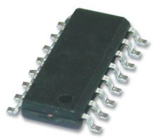
SSM2142SZ
Part Number: SSM2142SZ
Manufacturer: Analog Devices Inc.
Description: IC AUDIO 1 CIRCUIT 16SOIC
Shipped from: Shenzhen/HK Warehouse
Stock Available: Check with us
ICRFQ.com - Electronic Components Distributor in China Since 2003

Part Number: SSM2142SZ
Manufacturer: Analog Devices Inc.
Description: IC AUDIO 1 CIRCUIT 16SOIC
Shipped from: Shenzhen/HK Warehouse
Stock Available: Check with us
| Datasheet | |
|---|---|
| Category | Integrated Circuits (ICs) |
| Family | Linear – Amplifiers – Instrumentation, OP Amps, Buffer Amps |
| Manufacturer | Analog Devices Inc. |
| Series | – |
| Packaging | Tube |
| Part Status | Active |
| Amplifier Type | Audio |
| Number of Circuits | 1 |
| Output Type | Differential |
| Slew Rate | 15 V/μs |
| Gain Bandwidth Product | – |
| -3db Bandwidth | – |
| Current – Input Bias | – |
| Voltage – Input Offset | – |
| Current – Supply | 5.5mA |
| Current – Output / Channel | 70mA |
| Voltage – Supply, Single/Dual (±) | ±13 V ~ 18 V |
| Operating Temperature | -40°C ~ 85°C |
| Mounting Type | Surface Mount |
| Package / Case | 16-SOIC (0.295″, 7.50mm Width) |
| Supplier Device Package | 16-SOIC |
To clarify, the SSM2142 is a differential-output buffer amplifier. High-output-drive balanced signal pairs can be generated from a single-ended input signal. The SSM2142 aids in keeping the sound quality of audio systems consistent by filtering out power line hum, voltage drops, RF interference, and other forms of noise that can be caused by running audio cables over long distances. High gain precision is ensured by laser trimming of the onboard resistors, which also provides excellent rejection of common-mode noise and offset errors.
The SSM2142’s output stage is stable throughout a wide range of operating situations and can drive demanding loads with minimal distortion performance, even when connected by exceptionally long cables or with loads as low as 600. The SSM2142 is a completely balanced transformer alternative for line driving based on a cross-coupled, electronically balanced topology.
Yet, the SSM2142 achieves comparable common-mode rejection performance with fewer parts count while maintaining lower distortion and taking up considerably less board space than transformers. By combining the SSM2142 with the SSM2141 differential receiver, a full and trustworthy solution is established for driving and receiving audio signals over extended cable runs. The SSM2141 has a Common-Mode Input Rejection Ratio of 100 dB at 60 Hz. The typical system’s performance is detailed in the accompanying data sheet.
The following measurements show the usual performance of a balanced pair system employing the SSM2142/SSM2141 chipset and were collected from the THD test circuit of an Audio Precision System One with the internal 80 kHz noise filter. Differential and single-ended modes of operation are demonstrated, together with several output load circumstances meant to mimic real-world scenarios. Notice too that the use of the optional series feedback capacitors, which avoid optimal ac noise rejection by rejecting dc cable offsets has no negative impact on the performance of the system as a whole. Also displayed is the system’s large signal transient response to a 100 kHz square wave input, illustrating the reliability of the SSM2142.
The SSM2142 is well-suited for balanced line-driving applications due to its high levels of common-mode rejection, high output drive, and low signal distortion and noise. Two cross-coupled unity-gain buffer amplifiers with on-chip 50 series dampening resistors make up the differential output stage. During production, laser trimming is used to perfectly balance the impedances of the output buffer pair. As a result, the offset error voltages shared by the cable pair are effectively isolated from the desired differential input signal, and the gain accuracy required to effectively reject common-mode noise is achieved.
If you want your system to perform at its peak, you should utilize a balanced, high-input-impedance differential amplifier like the SSM2141 at the receiving end. In order to keep the system gain at 1, the SSM2141 receiver output is set up with a gain of 6 dB less than what the SSM1422 provides. DC blocking capacitors may be used at the SSM2142’s sense outputs in situations when a significant dc offset on the cable is present, or when optimal rejection performance is required by eliminating potential sources of differential offset errors. Components like the 10 F NP shown in the test circuit should have the lowest feasible impedance in order to reduce low-frequency mistakes (or tantalum if the polarity of the offset is known)
Since the ground potentials of the circuits at either end of a signal cable may not be identical due to ground currents, supply fluctuations, and other considerations, the signal must be amplified. In order to eliminate this voltage differential, often known as “longitudinal error,” a balanced pair line is used. Output common-mode rejection is an indicator of how well a system can filter out longitudinal error voltage. The following safety measures must be taken by the user in order to achieve the best possible OCMR and noise rejection performance with the SSM2142.
Finally, anyone wishing to filter and analyze damaged audio samples needs to look no further than Analog Devices’ SSM2142SZ-REEL differential amplifier. This single-channel IC has a differential output with a maximum of 18 V and can function between -40 °C and 85 °C while using two separate power sources. Contact ICRFQ to find out more about the SSM2142SZ-REEL and other electronic components that can help your ideas reach the next level. With their vast resources and expertise, ICRFQ can provide you with the necessary support to make informed decisions and bring your projects to life. So, don’t hesitate to take advantage of the available resources and start your next project with confidence. Contact ICRFQ today to order or learn more about the SSM2142SZ-REEL and other electronic components.
WhatsApp us