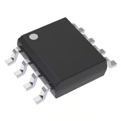
UCC2813QDR-5Q1
Part Number: UCC2813QDR-5Q1
Manufacturer: Texas Instruments
Description: IC REG CTRLR MULT TOPOLOGY 8SOIC
Shipped from: Shenzhen/HK Warehouse
Stock Available: Check with us
ICRFQ.com - Electronic Components Distributor in China Since 2003

Part Number: UCC2813QDR-5Q1
Manufacturer: Texas Instruments
Description: IC REG CTRLR MULT TOPOLOGY 8SOIC
Shipped from: Shenzhen/HK Warehouse
Stock Available: Check with us
| Datasheet | |
|---|---|
| Category | Integrated Circuits (ICs) |
| Family | PMIC – Voltage Regulators – DC DC Switching Controllers |
| Manufacturer | Texas Instruments |
| Series | Automotive, AEC-Q100 |
| Packaging | Tape & Reel (TR) |
| Part Status | Active |
| Output Type | Transistor Driver |
| Function | Step-Up, Step-Up/Step-Down |
| Output Configuration | Positive |
| Topology | Boost, Flyback, Forward Converter |
| Number of Outputs | 1 |
| Output Phases | 1 |
| Voltage – Supply (Vcc/Vdd) | 3.6 V ~ 12 V |
| Frequency – Switching | – |
| Duty Cycle (Max) | 49% |
| Synchronous Rectifier | No |
| Clock Sync | No |
| Serial Interfaces | – |
| Control Features | Frequency Control |
| Operating Temperature | -40°C ~ 125°C (TJ) |
| Package / Case | 8-SOIC (0.154″, 3.90mm Width) |
| Supplier Device Package | 8-SOIC |
The UCC2813QDR-5Q1 is an extremely versatile DC-DC controller IC that has been specifically designed to meet the demands of Boost, Flyback, and Forward Converter regulators. This IC provides a comprehensive solution for a wide range of power supply applications thanks to its ability to support positive output step-up and step-up/step-down operations.
The UCC2813QDR-5Q1 is available in an 8-SOIC package, which makes it compact and ideal for designs with limited space. With its robust features, efficient performance, and wide input and output voltage range, this device is an ideal choice for a variety of power conversion needs.
This guide will provide a comprehensive overview of the UCC2813QDR-5Q1 IC. We will examine its internal architecture, operation principles, design considerations, and application examples. Whether you are a beginner or an experienced engineer, this guide will give you a thorough understanding of this powerful DC-DC controller IC and help you effectively utilize its capabilities. Let’s delve into the fascinating world of UCC2813QDR-5Q1!
The UCC2813QDR-5Q1 is equipped with a strong internal architecture that consists of different functional blocks. These blocks collaborate to effectively regulate the DC-DC conversion process. These are the key components:
The driver circuitry serves to amplify the PWM signal and subsequently drive the power switch. It ensures efficient power switch operation and minimizes losses associated with switching.
The UCC2813QDR-5Q1 has important safety features built in to protect the IC and the whole power source system. Some of these things are:
The Boost converter is a common type of DC-DC converter design that regulates the output voltage by stepping it up. It is often used when the input voltage is lower than what is needed for the output voltage. When used with the UCC2813QDR-5Q1 IC, the Boost converter is an effective way to handle such situations. Let’s look at how the UCC2813QDR-5Q1 IC works in the Boost converter:
When the circuit is first turned on, the power switch (MOSFET) is on. This lets current pass from the input voltage source (Vin) through the inductor (L) and the power switch to ground (GND). The energy is stored in the magnetic field of the inductor.
When the power switch is turned on, the current in the inductor goes up, and energy is saved in the magnetic field of the inductor. The source (Vout) gets power from the output capacitor (C).
Turn off the power and let the energy out. The UCC2813QDR-5Q1 IC measures the feedback voltage and compares it to the reference voltage. When the current in the inductor hits a certain level that has already been set, the IC turns off the power switch. The energy that was stored in the inductor is now released.
When the power switch is off, the diode (D) conducts, allowing the current from the inductor to flow through the diode and the output capacitor to reach the load. This keeps the current from stopping and lets energy move from the inductor to the output.
As the inductor discharges, the energy stored in its magnetic field is passed to the output capacitor and the load. This raises the output voltage.
The process happens over and over again in a loop. Based on the feedback voltage, the UCC2813QDR-5Q1 IC controls the flipping of the power switch by changing the duty cycle of the PWM signal. This controls the output voltage.
The UCC2813QDR-5Q1 IC is a versatile and flexible DC-DC driver suitable for Boost, Flyback, and Forward converters. It provides the ability to step up and step down the output voltage. With its compact 8-SOIC package, wide input and output voltage range, and robust protection features, it is an excellent choice for efficient and reliable power supply solutions.
By utilizing its internal components, such as the error amplifier, oscillator, PWM comparator, and driver circuits, engineers have precise control over DC-DC conversion. In a Boost converter configuration, the IC works seamlessly with the power switch, inductor, diode, and output capacitor. By exploring the full potential of the UCC2813QDR-5Q1 IC, engineers can create flexible and adaptable power systems. To learn more about this product or to place an order, contact us at ICRFQ, the leading electronic component distributor in China. We are dedicated to providing high-quality products at affordable prices.
WhatsApp us